Results 1 to 10 of 15

Thread: My home made welder works

Hybrid View

Previous Post Previous Post   Next Post Next Post
  1. #1
    Join Date
    Aug 2007
    Location
    central central wisconsin
    Posts
    289

    Default My home made welder works

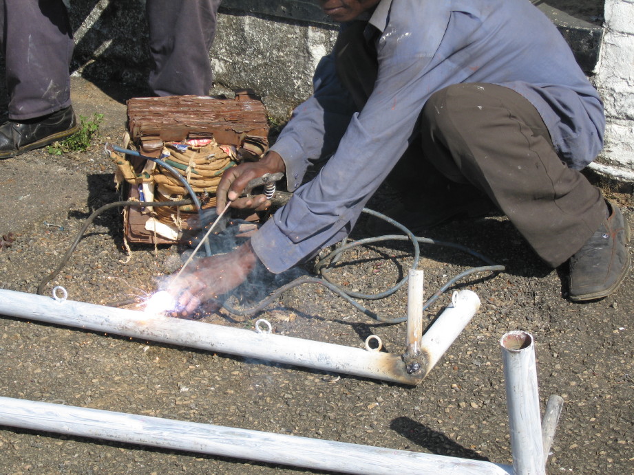
    I just finished my welder for the truck. I made it out of an alternator and set it up with a bracket on the engine as a separate alternator.

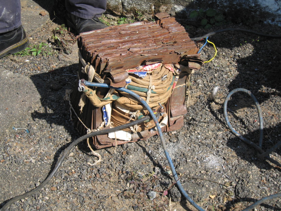
    here is a picture of the control box.


    The panel meters are for voltage into the field, the voltage output of the alternator which can exceed 140 volts I am told, and the amperage out. You really dont need anything but the voltage out, but I thought it looked cool and was curious about the amperage out reading. The voltage in, will now be a fixed 12 volts because of me not using the variable voltage input I was planning on from the start of the project. you would need this part of the circuit if you were to use a smaller engine or use a 220 volt motor to drive the alternator.

    I have it up and running at least. I still have to put on my vernier motor control and do some last minute work on the panel meters. I had some issues with everything so it took more time than expected to debug this one. The alternator I was using for this was set up for an external regulator so I thought it would be a plug and play thing, but after the truck stalled because the alternator was smoking, I took the alternator apart and found that the factory still places a diode inside for some reason or annother, and that diode shorted the output to ground causing the alt to put 200 amps directly to ground. I chucked the diode and everything is good now.

    Just because I could, I over complicated my welder with a bunch of things that were not really needed. I have simplified it greatly by getting rid of the variable voltage input for the field. The reason for this is that you can still vary the engine speed to get different voltages out of the alt. You really dont need or want the ability to adjust the input voltage because you would want your engine to be at the lowest RPM you can. For this reason, I am just putting in a full 12 volts into the alternators field. I have found that some if not all of the professional welders use a open circuit voltage of 38 volts. the reason for this, is two fold. To be safe for the public, you have to keep the voltage below 50 volts ( considered low voltage by the UL and therefore no need for extra safety measures) the other reason is just because it allows you to strike an arc very easily and welds very nicely, no need for higher voltage.


    An alternator welder is so easy to make, anyone can do it. If fact the most dificult part of the whole project, was to build the bracket for the engine to mount the alternator. I guess if anyone is interested, I can post some wiring diagrams or links that I thought were helpfull. I have found a lot of bad information out there on alternator welders. I am amazed at how easy this is to make. I think I am going to make one of these for each of my Jeeps, since it is cheap and easy.

    In a nut shell, this is what you need to do for the basic unit.

    Take the alternator apart and remove the regulator and the diode from the case then reassemble. (If you are using a GM alternator) for a Ford or Chrysler most have external which requires no mods or maybe just removing a diode inside the case.

    connect the Bat + on the back of the alternator to your welder stinger lead. ( this is called reverse polarity, but is absolutely necessary because to weld on your own vehicle, you need it. To weld on someone elses vehicle you could reverse them if you wanted.)

    Connect the ground terminal on the alt to the ground lead.

    run battery power through a 20 amp fuse then to a toggle switch and from the other side of the switch to the field terminal of the alternator. ( this gives full power to the alternator and will give you the alternators max output.

    Make some way for you to adjust the engines RPM. This could be a professional vernier cable or just a 10 speed bicycle shifter and cable. On my truck, Idle just happens to be 38.7 volts.

    This is the most basic setup, but you can add a couple extra things that make it even better.

    add a DC volt meter to this by connecting one lead of the voltmeter to each of the connections that your welder leads go to. ( this allows you to monitor the open circuit voltage and adjust your engines RPMs to the correct 38 volts or so, and it also will allow you to adjust the engines RPMs to give you 120 volts output.) If you have a tach, you could also measure the output with a hand held volt meter, and then see what RPM you need to get that voltage out. 2100 rpms = 38 volts so run it up to 2100 RPMs and weld. I bought mine from Ebay for about 10 bucks and is a cool blue LED panel meter. I would not recommend this one if your box will be under the hood though. water resistent is best for under the hood.

    add a 120 volt outlet to run power tools. Connect the gold terminal to the + stinger and the silver terminal to the - or ground. ( anything with brushes for the motor and does not have a variable trigger. Just run your RPMs up until the meter reads 110-120 volts and plug it in. ( I need to caution you though, this will also give you 120 volts at the welding leads, which can be dangerous if not handled correctly.) I have made my welding leads with quick disconnects so I can just disconnect them when I rev up the engine for the 120 volt power.

    You can use this as a power source to TIG weld also, or add a few parts and make it run a home made MIG welder.

    I have noticed that the alternator gets very hot even after one welding rod is used. I may add annother diode rectifyer to the back of the alternator I have, just to make it easier on the diodes. sometimes you can stack these so that you can divide the amperage load between the rectifyers. If you have questions, just ask.

  2. #2

    Default

    bCan you post some weld pics? I'd like to see how well a bead can be run, maybe penetration of the steel too. Thanks.
    "We are here for the meeting!"

  3. #3

    Default

    Can this be a sticky? I'm saving it on my computer too but...
    भगवान तुम्हें प्यार करता है

  4. #4
    Join Date
    Feb 2009
    Location
    Northern California
    Posts
    467

    Default

    I've long contemplated building one of those as well, but with a voltage regulator for the field, as you'd need constant voltage for MIG, regulating it at 120 for tools would be nice, it could provide a safe voltage limit when welding, etc, etc, etc.

    If you have problems with the diodes overheating, you could always run the stator windings out the back and use an external diode pack with some big diodes out of a real welder or such. I'm planning on doing this, both for extra power handling, and since I'd be sharing the alternator with the vehicle charging system, it'd make sure I didn't fry the diodes I needed to get home!


    My favorite homemade welder, that I found when looking up some info a while ago...


    (Not really on topic, as it's mains powered rather than vehicle-based, but always funny!)


    --Randy

  5. #5
    Join Date
    Aug 2007
    Location
    central central wisconsin
    Posts
    289

    Default

    I love that welder!! that is funny. If there wasn't a picture of them actually using it, I wouldn't have believed it worked.

    I have some pictures of my welding strenth test. I have to say, that even though I am good at MIG welding, I have not done any ARC welding in 20 years. and even then, it was only once to fix my mustang door when I was 15 years old. I have read that this alternator welder makes a novice weld very well compaired to using an AC welder because of the high frequency DC agitates the puddle. I could only find 1/8 th inch thick metal around, so I had to use that. This welder should be capable of 190 amps so it should be able to weld around 3/8 to 1/2 inch metal.

    I cut the weld apart half way with the grinder, then bent the rest of the metal until it broke. It broke next to the weld not at the weld, but it took several bends back and forth to do it. I did notice two black specs the size of a pin prick in the weld. not sure if this is typical, I don't have to check my welds when I do MIG since it is always good. I would really like to make a box to hold a spool of MIG wire and use a power window motor and gearbox to drive a set of metal wheels for the Mig wire. I could then use a standard MIG gun and just clamp my stinger to a stud on the outside of the box. I have never used flux core wire, but I would think that would be the best wire to run so I wouldnt have to deal with the tank and the extra wiring.


    I was having issues today with the welder because the belt was slipping. I don't know if it was because I painted the pulleys or because I used some really old rusty ones that were pitted. Either way I tightened the belts until they were guitar string tight, and that worked.

    here are some sites I found useful:

    http://home.comcast.net/~t.molnar/Obwelder4.htm

    http://mhickok.blogspot.com/2008/06/...rue-power.html

    http://www.justih.org/Binder-Bench/s...ead.php?t=4747
    Last edited by phoenix; April 11th, 2010 at 11:19 PM.

  6. #6

    Default

    This is a really great thread. I love the welder you made Phoenix.

    I bought a used premier power welder for a real good deal. It was still a pile more than your project. I have sent it back once and I just had to replace the main solenoid for 50 bucks recently. My main charge circuit goes through the welder. It failed because the switching solenoid I just mentioned puked. Keep it simple. Always keep it simple. Good post.

    Just in case. We tore a frame rail in half one year while rock crawlin. This is how we fixed it.
    In an emergency and you have 2 good car batteries, metal files to join them, Visegrips to clamp them and jumper cables to weld with, you can weld a frame back into one piece. 3 batteries is to much. It will vaporize the rod and not weld well. I have done this and it works pretty well. It is not adjustable like above, but it got us home.

    It would be cool to adapt a fan clutch on an alternator.
    Liz, covid, murdered 10/19/21

  7. #7
    Join Date
    Aug 2007
    Location
    central central wisconsin
    Posts
    289

    Default

    The MIG welders would really need to be variable voltage since it is critical at what voltage you are running for the thickness of metal you are working with. 17 volts works great for 20 gauge and 21 volts works great for 3/8 thick steel. If you used a regulator, you would have to use several regulators to get a few settings. My thought was to keep it the way I have it so that you can vary the voltage with the RPMs and since MIG wire is so small, I doubt that the motor would drop down in RPM that bad and therefore would keep a pretty accurate voltage. The same applies for the 120 volts out. As long as the amperage draw does not get so high that the engine boggs down, the voltage should stay pretty close. you really dont need exactally 120 volts anyway just get it close. 90-130 could even work. I noticed that my voltage started at 38 volts when I first started the engine, but after it warmed up it changed to around 46 volts.

    I thought about using some external diodes, but it complicates things a lot more. I found out that some of the aftermarket alt rebuilders use two and three rectifyers piggybacked on the back of the case. Some alternators out there are rated at 500 amps now. My alternator already has some holes that will allow me to add one or two more rectifyers. I am not sure what they cost or if my alternator has a special case or not.

    My alternator is an aftermarket one that someone gave me for free. it is a 190 amp alt but is based off of a GM CS144 found on mid 90s cars. The stock CS144 puts out 140 amps and is the highest I have seen for stock. Ford 3Gs put out 130 amps stock. You can also buy them off of Ebay like I did for my alt that charges the battery in my truck. I paid 109.00 for a modified 3G ford alt that was remanufactured with new windings new american components and is now rated at 200 amps output.


    I wanted to use the same alt for charging and welding but it just doesnt make sense to do this since it puts such a strain on the alt it can burn out and wiring it to do both makes the engine run off the battery while you are welding so it limits your welding time before you need to switch it back over and charge the battery. It would also add a bunch more wiring to add an external regulator This thing gets so hot, I am afraid to weld more than one stick before I let it cool off. You cant put your hand on it.

    The only reason I would consider running one alt for charging and welding is if there is no room in the engine compartment left to mount a second alt. Say you dont have enough room under the hood. You could always make a bracket to mount the alt but not be able to shut the hood. make it so the alt would be just a simple bolt on deal and tighten the belt and go. When your done, take the alt off and put it back in your carrying box along with your wires.

    Now I just need to make an on board air compressor system for my truck using a York air conditioning compressor (I made one for my Jeep TJ years ago).

Similar Threads

  1. Made it Home
    By Pineyguy in forum Open Discussion
    Replies: 8
    Last Post: January 14th, 2008, 12:37 PM
  2. Home made trans adapter
    By wrecker in forum Modified Tech
    Replies: 17
    Last Post: October 2nd, 2007, 10:33 PM

Posting Permissions

  • You may not post new threads
  • You may not post replies
  • You may not post attachments
  • You may not edit your posts
  •  


Site Upgrade, Design Modifications & Administrative Support by:
Palm River Enterprises LLC, IT Solutions
President: Tom King, User ID=teking
This site is owned and operated by:
M715 Zone, LLC
President: Jon Schmidt, User ID=brute4c


If you have any suggestions, comments, problems or questions, contact:  brute4c@m715zone.com
Use of this site means you understand and agree to our TERMS OF USE

Copyright Notice:
This web site is subject to the protection of the copyright laws of the United States and other countries. Except for Personal Use Only, you may not modify, copy, distribute, transmit, display, perform, reproduce, publish, license, create derivative works from, transfer, or sell any information obtained from any part of the M715 Zone website without the prior written permission of M715 Zone, LLC. Written permission can only be obtained by contacting brute4c@m715zone.com

Copyright 1998-2024